


Composite deck
1. INTRODUCTION
1.1 Definition
A composite deck consists of a cold-formed profiled steel sheet covered with a concrete slab containing reinforcement (see Figure 1). Such slabs are generally used in frame structures, with steel floor beams, as discussed previously in Composite construction - general. They can also be used in combination with other materials.

In this type of construction, the profiled sheet has several functions:
- it provides a working platform for construction
- it acts as formwork for the concrete slab
- it constitutes bottom reinforcement for the slab
The present lecture is mainly concerned with composite slabs when the steel-concrete bond has been formed, i.e. after hardening of the concrete. Design for the construction stage, when the profiled steel sheet supports the weight of wet concrete, is only considered briefly.
1.2 Types of profiled sheet
There are many types of profiled sheet used for the construction of composite slabs (see Figure 2). These types vary in form, rib depth, rib spacing, sheet size, style of lateral over-lapping; in the methods of stiffening the flat elements of the profile; and in the methods of mechanical connection which ensure bond between the steel sheet and concrete slab.


The thickness of the sheets can vary from 0.75 mm to 1.5 mm, but in normal practice it lies between 0.75 and 1.0 mm.
The height of the profiled sheets can vary from 40 mm to 220 mm.
Whatever the particular requirements for a steel framed building, it is probable that they can be met by using a profiled sheet from this range, as the typical criteria for sound insulation, fire protection, maximum span, and maximum load can easily be met.
1.3 Steel-concrete connection
The bond between the concrete slab and the profiled sheet must be capable of transmitting longitudinal shear at the steel-concrete interface.
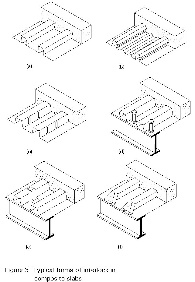
This connection can be made in one or more of the following ways, as shown in Figure 3 (which has been taken from Fig. 9.1 of Eurocode 4 [1]):
- by the re-entrant shape of the ribs creating bond by friction (see Figure 3a, b)
- by embossments on the flanges or ribs of the sheet (see Figure 3c)
- by anchorages situated at the ends of the slab, consisting of stud connectors welded through the sheet (see Figure 3d), shot-fired shear connectors (see Figure 3e), or by deformation of the ribs (see Figure 3f)
Read more