


More case studies with European sections
Similar case studies Airports
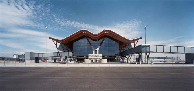
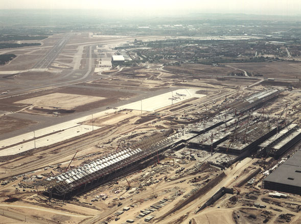
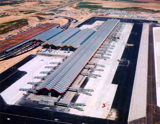
Terminal 4 Madrid-Barajas Airport: An undulating roofscape supported by ArcelorMittal steel
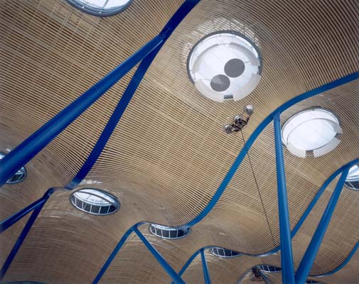
A homogeneous building complex with clearly structured buildings, a corrugated roofscape with skylights and bamboo ceiling, a steel roof structure in rainbow colours for clearer orientation, and the optimisation of natural light makes the award-winning Terminal 4 complex at Madrid-Barajas Airport one of Europe's most modern airports. ArcelorMittal supplied hot rolled sections and heavy plates for this infrastructure project.


Detailed information
T4: Concept & buildings
Terminal 4 at Madrid-Barajas International Airport, opened in 2006, was devised in response to the spectacular growth undergone in the world's air transport over the years with the aim of creating a new hub in the south of Europe to be mainly used as a connection point for flights between Europe and Latin America.
The project includes a simple configuration formed by three buildings: a terminal Building, a satellite building and a car park.
Terminal building
Designed to provide for domestic and Schengen traffic, the T4 Terminal building spans over a total area of 470 000 m2 and reaches a maximum dock length of 1142 m.
The building is set up in three parallel volumes separated by inner courtyards, so-called "canyons," that allow for the penetration of natural light at six levels: three above ground and three below ground.
Closest to the access area, the first volume accommodates, at various levels, 174 check-in desks and the arrival hall as well as the customs offices. The second building shelters the security control facilities and the commercial area. The third volume, the dock, holds departure lounges and boarding areas with direct connection to the planes through 36 gates in addition to the underground platforms to access the automatic trains connecting the terminal and the satellite buildings.
Satellite building
The satellite building, two kilometres away from the terminal building and located between the four runways with an area of approximately 315 000 m2, mainly provides for international flights.
Similar to the terminal building configuration, two separate volumes can be distinguished in this building with only one canyon and six levels in each of them. The first volume accommodates the passenger boarding and landing dock with a length of 927 m in which two levels can be distinguished. It is equipped with 26 boarding gates, of which 16 are double gates - capable of providing for two airplanes at the same time. The second volume, which runs parallel to the previous one, is designed to shelter passport control and commercial areas.
Car park
With a total capacity exceeding nine thousand parking spaces, the parking area, integrated by six five-storey modules, is connected to the terminal building by two footbridges that cross the vehicle access areas and the rail and underground station at an intermediate level between the departure and arrival premises.
Subterranean connection tunnel
A service tunnel under the runways was designed to facilitate the movement of passengers, goods, and baggage between the terminal and the satellite buildings. Supply vehicles, moving walkways, and the Automatic System of Baggage Processing (SATE) run through this tunnel.
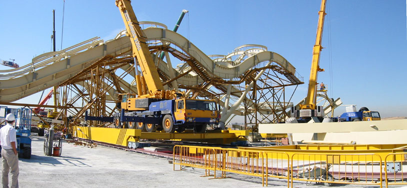
T4's steel structure
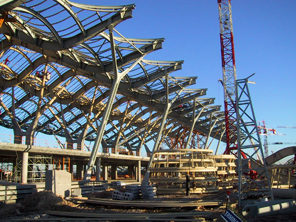
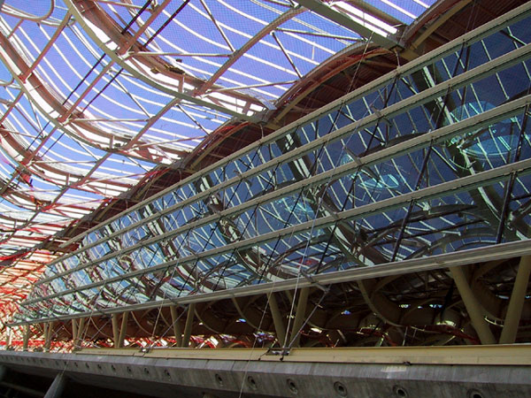
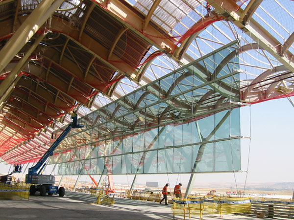
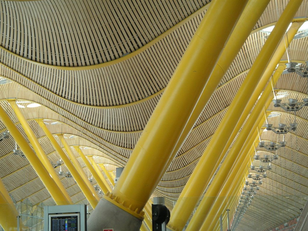
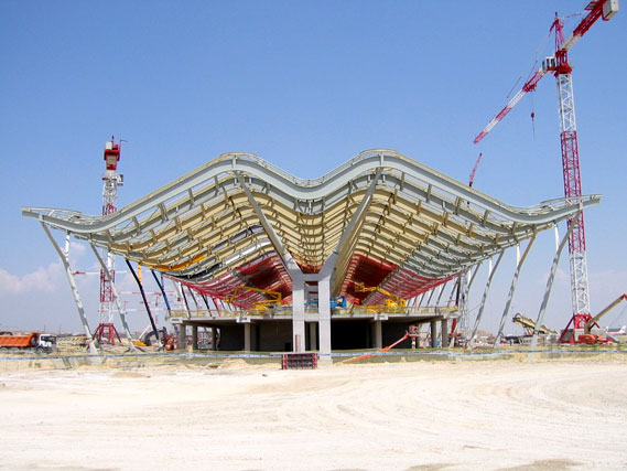
From a structural standpoint, the basic element of the terminal and the satellite buildings is a system of post-stressed concrete beams and columns from which metal supports branch off that support the winding main beams of the building roof.
Thus, a double-curvature, modular, and repetitive surface is generated that spans over the entire area occupied by the buildings. A highly remarkable feature in the structural design is that the facade curtain wall contributes significantly to the stability of the assembly by bracing the roof structure to the concrete beams by means of a system of stainless steel rods distributed over the entire building perimeter.
Main beams: With a length of 72 m, on-site measured, and arranged at 9 m from each other under the entire roof surface, the main beams allow for a geometric profile that has a great relevance to the eye-catching shape of the building. These seagull-wing profiled beams are symmetric I sections with variable edge dimensions, ranging from a 1500 mm depth in the centre to a 750 mm depth in the area of the leaning shores. The wings have a section of 500 x 30 mm, with the web being made of 15 mm thick plate.
For this, steel grade S355 J2G3 was selected except in the areas with higher curvature radii where, due to the stress increase produced by the deviation of the longitudinal strains, it was necessary to use a higher steel grade in the wings (S420N).
Forming arches between the main beams, perpendicular secondary beams were used leaving a 3.5 m span between them. They were fabricated from rolled sections (IPE-500, HEB-500, and HEB-700) in grade S355 J2G3 that support UPN-100 purlins in grade S275, on which the roof surface leans.
A special bracing system was set up to prevent buckling in some components along the roof, to distribute horizontal forces, and to optimise load transmission to the support elements.
Expansion joints are arranged at 72-m intervals to correspond with the building expansion joints, placed cross-sectionally on one the sides of the main beam, with a sliding bearing system for all the secondary beams set on to it.
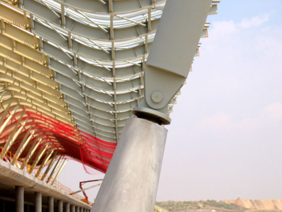
Metal V-supports: Each main beam has four support points - two in the centre and two on the sides - all of which lean on metal supports embedded in concrete plinths of a special design for the building structure support.
The trunco-conical central supports are inclined forming a V with a section of 750 mm in the base and of 400 mm at the head. These elements were fabricated from 16-mm thick S355 steel plate and are joined to the main beams by means of a spherical joint with a 42 CrM04+QT steel pin.
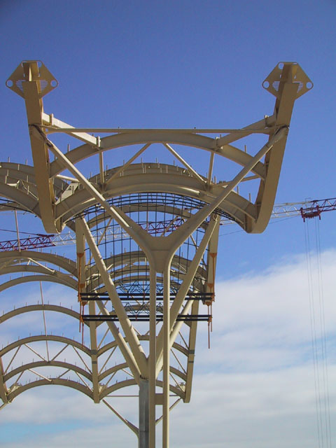
Metal Y-supports: The support points of the main beam ends consist in Y-shaped columns at an angle of 19º. Like a Y letter, the top section branches off in two separate arms each supporting a main beam.
The selection of this structural option gave rise to a significant architectural constraint: these elements must cause minimum visual impact through the facades while contributing, at the same time, to the spatial definition of the canyons.
They are formed by two elliptical tubes made of 14-mm thick steel plate in grade S355 with sections of 480 mm and 240 mm. Even though they receive only a vertical reaction and despite their inclination and Y-shape, a very important bending effect is generated, partially reduced by the stays located at the head of either arms and by the bottom flexible connection.
In the sections where they run parallel, these tubes are plate-joined at different heights, thus yielding a performance equivalent to that of battened columns. The arm top sections are joined by a tubular stay (Ø159.20). The bottom support is articulated by means of a 42 CrM04+QT steel pin, whereas the upper end is joined to the main steel beam using a spherical joint with a 42 CrM04+QT steel pin.
The fabrication of Y-shaped steel supports
The elliptical tubes (Ø480x240x14 mm) are manufactured by a precision hot-bending process following induction heating of the material. In this operation, made at temperatures ranging from 800 to 900 ºC, a combined bending and compression stress is applied depending on the tube axis.
The process can be described as follows:
Originally, the tube is positioned so that the inductor ring meets the defined curve development point. Once the tube is correctly positioned and with a hydraulic clamp holding its head end, the bending process starts. The inductor ring heats a tube zone until the initial temperature is reached. At that moment, as the tube is pushed from the back end and as the clamp starts moving along a circumferential rail, a bending effect is produced which makes the tube zone under the inductor ring become curved. The temperature at this section is controlled by two optical thermometers, focussing on the extrados and the intrados respectively.
To position the tube correctly on the machine when the section has only one curve or when the curve to be obtained is the first of a series, it is sufficient to set the generating line previously defined as extrados in the outer section.
This type of bending process causes the tube microsections to be heated and cooled in a quick and immediate action (thanks to a light and continuous water spraying operation to prevent material damage). As the holding time at the bending temperature is minimised, no material transformation occurs, except for a minor grain refining in the material bent due to the physical effect associated to the compressive effort caused on the hot section when the tube is pushed from the back.
Project information
- Madrid
- Spain
- Architect:
Estudio Lamela and Richard Rogers Partnership - 2005
- Client:
AENA - Engineering Firm:
Structure: Anthony Hunt Associates, TPS with OTEP; HCA SERVICES. Installations: TPS; INITEC. Façade: OAP Façade Engineering. - Contractor:
Dragados and FCC. - Photographer:
Estudio Lamela