


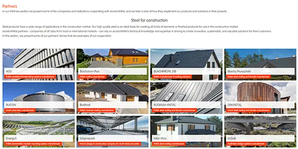


More case studies with Floor profiles
More case studies with European sections
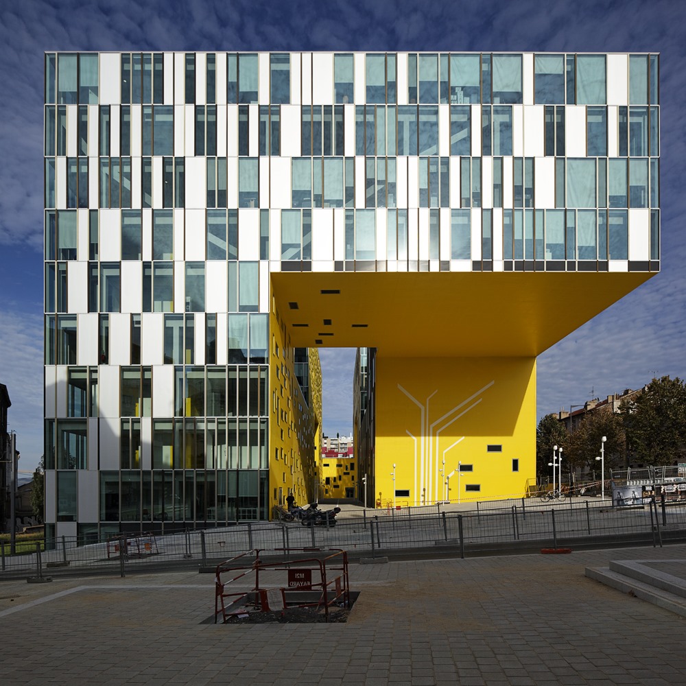
A combination of architectural aspirations and different structural principles in the Cité Des Affaires Business Centre
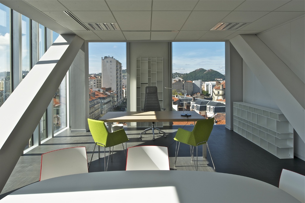
For the architect, this building in the form of an Aztec serpent is characterised by volumes that are sometimes ground-hugging and sometimes soaring. It incorporates two large gateways and a third cantilevered porch that comprise the distinctive features of this office building. ArcelorMittal delivered structural sections and a composite floor solution for this modern project.


Detailed information
Objectives of the project
Saint-Etienne’s 'Cité des Affaires' is located on the Avenue Grüner island site in the Châteaucreux district. It is an office building intended to accommodate primarily various public bodies but also private companies.
The building extends over eight storeys plus a mezzanine with a canteen on the ground floor and a 4-storey, 402-space underground car park. It will accommodate 1500 work stations.
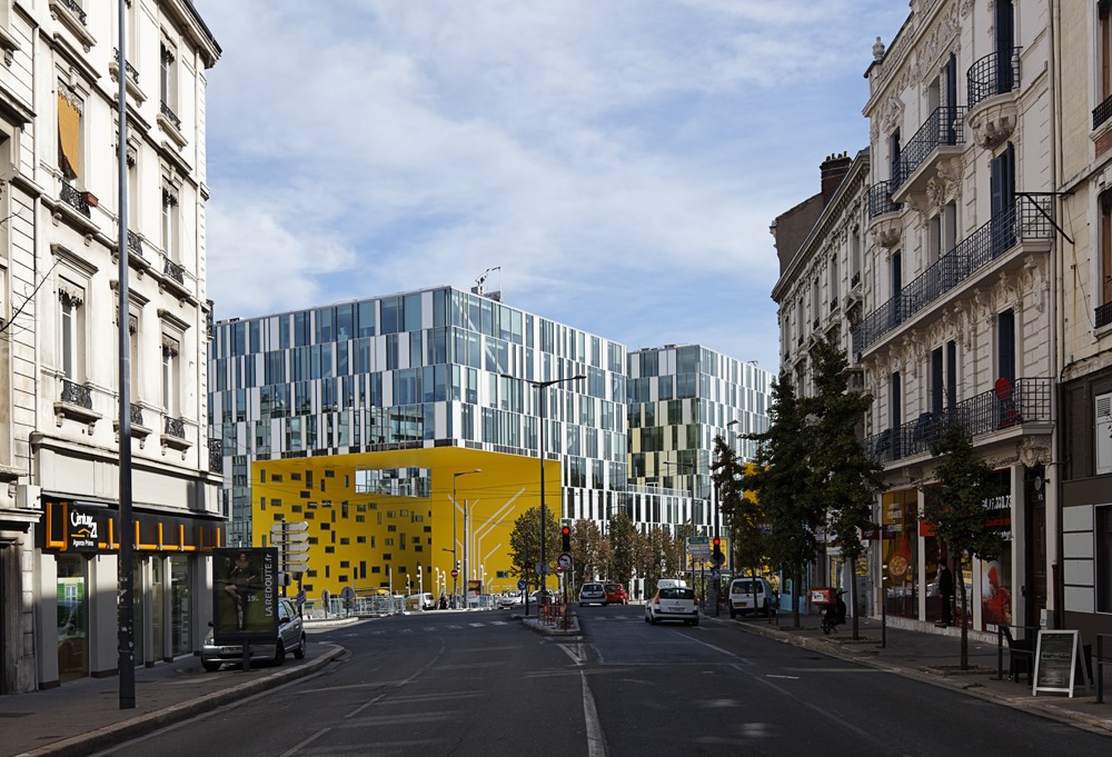
The plot allocated for the project is located near the Saint-Etienne railway station in a district scheduled to undergo change and active intensification.
To address this future, the idea was to create a continuous but sinuous volume that sometimes rests on the ground and sometimes detaches itself from it to form large gateways and overhangs above the site.
The continuity of this volume makes it possible to provide excellent flexibility: At any time, users can arrange themselves to increase or decrease their area to the benefit or detriment of the other.
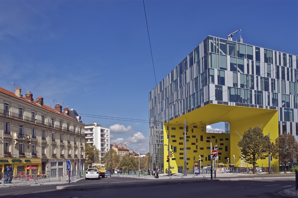
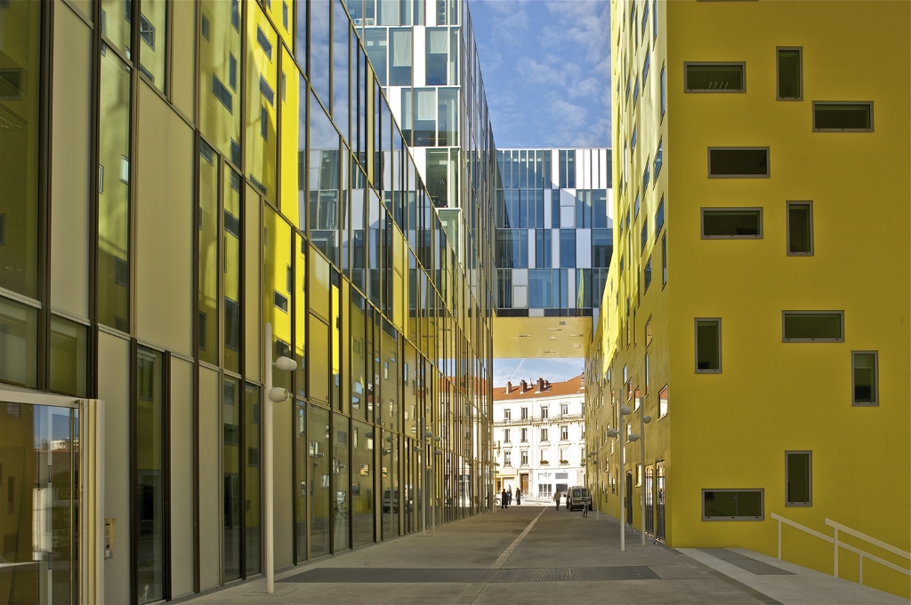
This 'Aztec serpent' project expresses the undulating motion that it adopts when it rests on the ground or rises in large gateways that provide openness to the exterior. There are three offset giant gateways providing vistas and pedestrian transit in all directions.
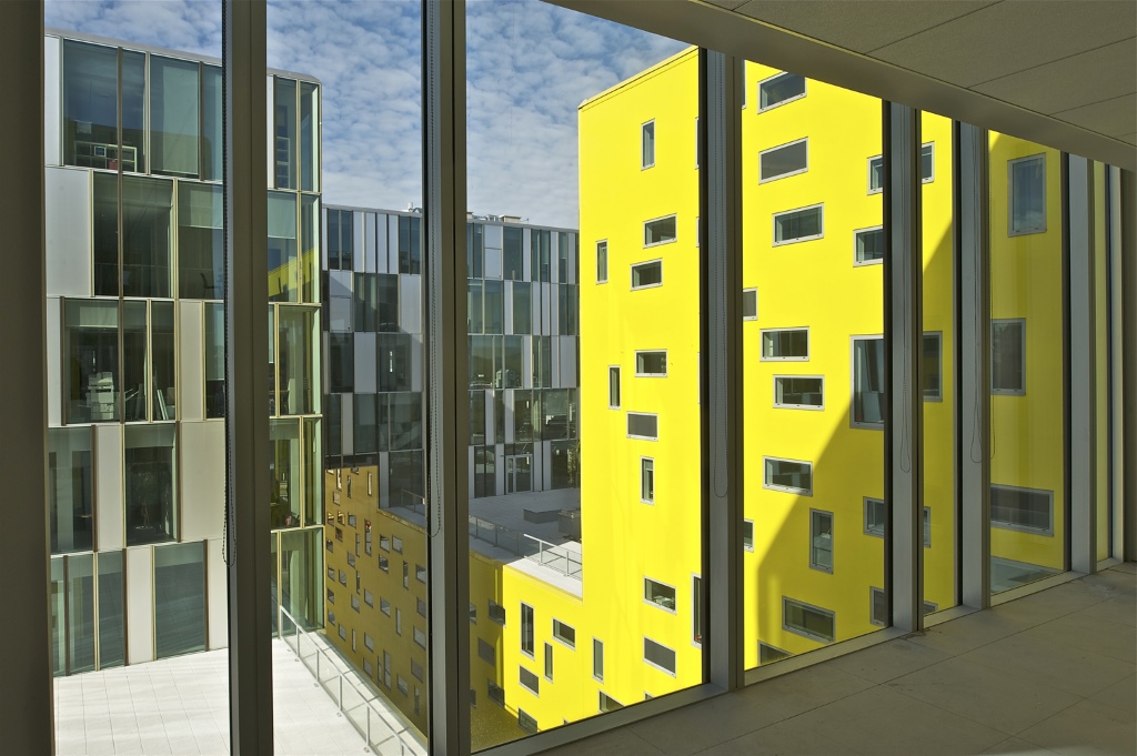
This volume is glazed on three facades and yellow on the fourth. Like luminous highlighting, the yellow facade brightens the interior of the complex and accentuates the general readability of the angulations.
The construction system comprises concrete columns and beams for the office floors with concrete loadbearing walls for the spaces overlooking the plaza. Steel frames were used for the portal or cantilevered parts. A curtain wall was used on the street facade and an aperture with a frame in a concrete curtain wall overlooks the plaza.
General description of the building
The building housing Saint-Etienne’s future Cité des Affaires rises within the spatial envelope of an almost rectangular parallelepiped approximately 108 m long, 44 m wide, and with a maximum height of 35 m.
This parallelepiped incorporates recesses and hollows as a result of:
- the incorporation of flat roofs at varying heights in respect of the main sections of the building
- penetration by an internal street thus creating two longitudinal wings, one located along Rue Bérard and the other along Rue de la Montat
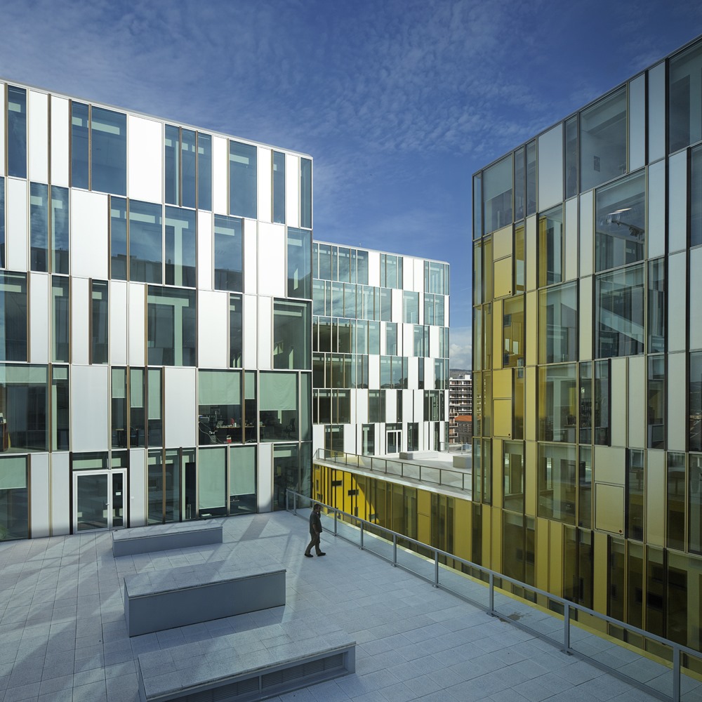
- the creation of a plaza at the corner of Rue de la Montat and Avenue Grüner by means of a recess in the Montat wing, from ground floor to third floor level
- the creation of two porch apertures, one through the Montat wing and the other through the Bérard wing, by creating an aperture in each of these two wings, over a width of 20 m from ground floor to third floor level in one case and to fourth floor level in the other
This creates a succession of contiguous buildings extending along the internal street and forming, according to the case in point:
- building sections resting on the infrastructure elements, with a building height plan ranging from 4 to 10 storeys
- two portal sections spanning the porches over a width of 20 m
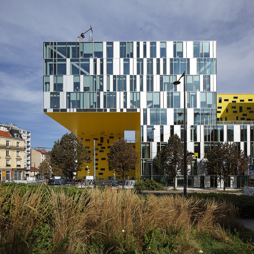
- a cantilevered section situated above the plaza at the end of the Montat wing with an overhang of approximately 19 m, turning above the internal street to the Bérard wing with an overhang of approximately 25 m
Technical principles of the main superstructure
While the architectural aspiration was to create a visual continuum like a ribbon that unfolds, there are actually three different structural principles according to the section of the building in question:
- building section resting on the infrastructure elements
- 'portal' building section
- cantilevered building section
Building section resting on the infrastructure elements
The frame of these building sections is reinforced concrete. It incorporates vertical circulation nodes (stairs, lifts, shafts) and floors with a frame of solid columns, beams, and slabs. The columns and walls are supported by the infrastructure’s vertical loadbearers.
'Portal' building section
The frame of each of these two 'portal' buildings comprises two parts:
- The bottom storey of the portal building performs the structural function of load transmission above the porch. It comprises four rows (two rows on the facades and two internal rows) of embedded steel truss girders with embedded nodes whose bottom chord is located in the floor of the bottom storey and whose top chord is located in the ceiling of the bottom storey. The diagonals of the trusses are therefore located in the volume of the bottom storey of the portals, behind the facades and along the internal circulations. The floors and ceilings of the bottom storey consist of steel joists and structural floor troughs with a reinforced concrete compression slab and rest on the four truss girders.
- The upper levels, whose framework consists of reinforced concrete columns, beams, and solid slabs, with the columns resting on the truss girders of the portal’s bottom storey.
Cantilevered building section
The frame of the overhang consists of a steel framework and structural floor troughs with a reinforced concrete compression slab on steel joists.
The steel frame ensures the rigidity of the cantilever in both directions (main cantilever in the axis of the Montat wing and secondary cantilever in the axis perpendicular to the Bérard wing) and the transmission of loads to the curtain walls and reinforced concrete cores of the buildings resting on the infrastructure elements at the end of the Montat and Bérard wings.
The vertical forces of gravity of the cantilevered frame to be transmitted under these conditions can be broken down into:
- inclined compressive forces transmitted to the loadbearing walls positioned on the edges of the cantilevers by struts installed in each of the two directions in four rows (two rows on the facades and two internal rows)
- horizontal tensile forces transmitted by beams located within the thickness of the floors to the reinforced concrete cores that also take up the horizontal component of the inclined compressive forces transmitted by the braces on the loadbearing walls
These cores therefore ensure the overall stability of the entire structure influenced by the eccentricity of the cantilever frame’s gravity loads in relation to its foundations.
Additionally, steel web system elements are arranged in the floors to provide transverse monolithism of the cantilever frame both locally and in its entirety (anti-buckling of struts, absorption of horizontal loads due to wind, etc.).
Infrastructure
The superstructure works described above rest on two infrastructure levels used for car parks, archives, and miscellaneous other uses. The whole has its foundations on reinforced concrete piles anchored in the schistose to schisto-sandstone bedrock, beneath the karstic layers of the carbonaceous shale.
A high-performance facade
The facade design was conceived to address an architectural, programme-related, geographic, and economic scenario and to afford unrivalled thermal performance.
The principle of the facades is based on the complementarity of a glazed skin and a mineral skin where each performs its function, and on the variation in energy, thermal, and spectrophotometric performance of the envelope according to the project’s various geographic and urban orientations.
Increased thermal capacity was achieved by means of:
- Large areas of double-glazing with 16 mm argon-filled space with high thermal performance, balancing light transmission and thermal insulation by means of good spectrophotometric properties TL 60%, FS 31%, Ug = 1.1 W/m².°C.
- Optimisation on the curtain wall facade by means of alternating glazed and opaque modules, enabling attainment of an overall Ucw = 1.5 W/m².°C. The opaque modules constitute 30% of the 10 000 m² total area of the curtain wall facade.
- Sandwich panels consisting (from exterior to interior) of an of anodised aluminium panel, thermal, and acoustic insulation and a thermolacquered steel sheet.
- A construction principle of the curtain wall which is based on a structure made up of independent prefabricated frames manufactured from thin aluminium sections with a thermal break, enabling total control of its permeability to air.
- Additional comfort achieved by the use of a mineral wall in which are implanted independent frames, contributing thermal inertia on the inner street facades.
- On the mineral facade (20 to 40 cm thick loadbearing concrete facade) with internal insulation, glazed frames are arranged in a random manner on the external face of the wall. The glazing is identical to that of the curtain wall and therefore has the same thermal performance.
Substantial light input
This light input, which allows for pleasant working conditions, is provided on the curtain wall facade by:
- A choice of suitable glazing to address the various exposure requirements; thus, the facades not exposed to the sun were fitted with clearer glass with a light input with a TL of 75%.
- Optimisation of the end fittings on the underside of the floor on the curtain wall facade that enables full-height glazing, allowing light to penetrate further inside the offices, thus contributing to reduced consumption for artificial lighting.
- Optimisation of light input by the installation of glazed frames on the exterior surface of the mineral wall, thus enabling diffusion of light by reflection on the reveals and sills.
- Better light distribution inside the floorplates through a variation in the location of the glazed frames in relation to the floors, and frames that are, moreover, arranged in a vertical or horizontal format.
Project information
- Saint Etienne
- France
- Architect:
Manuelle Gautrand - 2008-2010
- Engineering firm:
Debray Ingénierie - Khephren - Arcora - Contractors:
Altaréa-Cogedim, Baudin-Châteauneuf - Photographers:
©Philippe Ruault, ©Vincent Fillon